A Review of NIST Projects in Surface and Topography Metrology for Firearm Evidence Identification in Forensic Science
John Song
DOI10.21767/2472-1948.100004
1National Institute of Standards and Technology (NIST), Gaithersburg, MD, USA
2University of Warwick, Coventry, UK
- Corresponding Author:
- John Song
National Institute of Standards and Technology (NIST)
Gaithersburg, MD, USA.
Tel: 301-975-3799
E-mail: song@nist.gov
Received date: January 19, 2016 Accepted date: February 03, 2016 Published date: February 10, 2016
Citation: Song J, Liu X. A Review of NIST Projects in Surface and Topography Metrology for Firearm Evidence Identification in Forensic Science. J Sci Ind Metrol. 2015, 1:4 doi: 10.4172/2472-1948.100004
Abstract
This is a review of the National Institute of Standards and Technology’s (NIST) efforts in surface metrology and topography measurements for firearm evidence identifications in forensic science. Based on the research projects in surface metrology and standardization, NIST researchers have developed Standard Reference Material (SRM) Bullets and Cartridge Cases (Certain commercial equipment, instruments, or materials are identified in this paper to specify adequately the experimental procedure. Such identification does not imply recommendation or endorsement by the National Institute of Standards and Technology, nor does it imply that the materials or equipment identified are necessarily the best available for the purpose) and established a 2D/3D Ballistics Topography Measurement System. They formulated a Traceability and Quality System to support nationwide ballistics identifications within the National Integrated Ballistics Information Network (NIBIN) in the United States. They have recently proposed a Congruent Matching Cells (CMC) method for accurate ballistic identification and error rate estimation, which provides a statistical foundation and a practical method to promote firearm evidence identifications from qualitative image comparisons to quantitative topography measurements.
Keywords
Forensic science; Firearm identification; Surface metrology; Error rate; Congruent matching cells; CMC
Introduction
When bullets and cartridge cases are fired or ejected from a firearm, the parts of the firearm that make forcible contact with them create characteristic toolmarks on their surfaces called “ballistic signatures” [1]. Striation signatures (2D profile toolmarks) on a bullet are caused by its passage through the gun barrel. Impression signatures (3D topography toolmarks) on a cartridge case are caused by impact with the firing pin, breech face and ejector [1]. By microscopically comparing these ballistic signatures, firearm examiners can determine whether a pair of bullets or cartridge cases was fired or ejected from the same firearm. Firearm examiners can then connect a recovered firearm or other firearm evidence to criminal acts [1].
The field of firearm evidence identification is more than 100 years old and the field of surface topography is at least 80 years old, but the combination of the two-using topography measurements and correlations for identification of fired bullets and cartridge cases-has only been around for about 15 years. The combined field is so new that current firearm identification at crime labs for bullets or cartridge cases are still performed manually by experts in side-by-side image comparison using optical microscopes; and the conclusion of a “match” or ‘non-match” is mainly based on experts’ experience. Nevertheless, this interdisciplinary field brings a vision that one day firearm related investigations and identifications might be accomplished or affirmed through database searches using surface measurement data of the ballistics evidence and automated correlation programs, both are based on surface and topography metrology. Further, a conclusion that certain firearm evidences is a match or a non-match could include an uncertainty (or error rate) report, which could also be developed from surface and topography metrology [2].
In this paper, we discuss challenges to firearm evidence identifications, followed by development of standard bullets and cartridge cases and a 2D/3D topography measurement system, and the formulation of a traceability and quality system and error rate procedure for firearm evidence identification in forensic science.
Challenges to Firearm Evidence Identifications in the United States
Despite a long history of use in court, the scientific foundation of firearm and toolmark identification has been challenged by recent court decisions and by the 2008 and 2009 National Academies Report [3,4]. We review a series of NIST research projects addressing these challenges, which are aimed at providing scientific support to firearm evidence identification in the United States:
• Developing reference standards—NIST SRM (Standard Reference Material) 2460 Bullets and SRM 2461 Cartridge Cases for instrument calibration and establishing a measurement traceability and quality system to support nationwide firearm identifications [5].
• Developing a 2D/3D Ballistics Topography Measurement System [6,7].
• Developing a Traceability and Quality System using NIST SRM Bullets and Cartridge Cases [8,9].
• Developing a Congruent Match Cells (CMC) method for accurate ballistics identification and error rate report [10-14].
The SRM Standard Bullets and Cartridge Cases are Manufactured by the Same Techniques Used for Manufacturing Surface Roughness Specimens
As a reference standard for ballistics signature measurements and firearm evidence identifications, basic technical requirements for NIST SRM 2460/2461 Standard Bullets and Cartridge Cases are specified [5]:
• Real firearm surface characteristics: The bullet and cartridge case signatures must be obtained from fired bullets and cartridge cases, which are duplicated on the surface of the physical standards—the SRM Bullets and Cartridge Cases with high fidelity. The shape, size, material and color of the physical Standard Bullets and Cartridge Cases should be as close as possible to those of the real bullets and cartridges.
• Repeatability and reproducibility: As a measurement standard, the profile signatures on the SRM Bullets and Cartridge Cases must show such a high degree of repeatability and reproducibility that when these SRM standards are distributed nationwide for checking instrument calibrations, they all play the same function as a single SRM standard does. Repeatability here means that the profile signatures are essentially identical over different SRMs produced at the same time. Reproducibility means that the profile signatures are highly uniform among different SRMs produced over time.
• Measurement traceability: The profile and topography measurements for SRM Bullets and Cartridges performed at NIST Surface Calibration Laboratory must be traceable to the SI unit of length. By using these SRM Bullets and Cartridges, ballistics signature measurements using optical techniques performed at local forensic laboratories can be traced to the Bureau of Alcohol Tobacco and Firearms’ (ATF) image standard established at ATF’s National Laboratory Center using the SRM Bullets and Cartridge Cases.
• Information technology: It is advantageous to base the SRM Bullets on information technology. Then the digitized profile signatures may be stored in a computer, and used to produce and re-produce the identical SRM Bullets at any time.
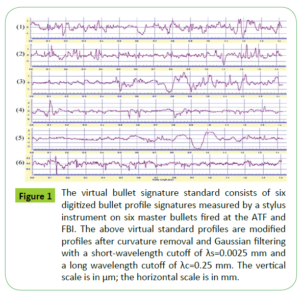
Based on the technical specifications, the SRM bullets were designed as a virtual/physical bullet signature standard [5]. The virtual standard is a set of six digitized profile signatures based on six fired bullets at the National Laboratory Center of ATF and the Central Laboratory of the Federal Bureau of Investigation (FBI) using six different guns under standardized firing conditions. These master bullets underwent profile measurements at NIST’s Surface Calibration Laboratory using a commercial stylus instrument. Each bullet was traced along one selected Land Engraved Area (LEA). The resulting set of six digitized bullet profile signatures was stored in a NIST computer as the virtual standard for both the fabrication and measurement of SRM bullets [5] (Figure 1).
Figure 1: The virtual bullet signature standard consists of six digitized bullet profile signatures measured by a stylus instrument on six master bullets fired at the ATF and FBI. The above virtual standard profiles are modified profiles after curvature removal and Gaussian filtering with a short-wavelength cutoff of λs=0.0025 mm and a long wavelength cutoff of λc=0.25 mm. The vertical scale is in μm; the horizontal scale is in mm.
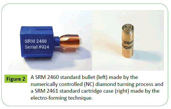
The Engineering Physics Division at NIST has a long history of developing surface roughness specimens [15-17]. In 1998, a virtual/physical random profile surface roughness standard was developed at NIST using a numerically controlled (NC) diamond turning process at the NIST’s Instrument Shop [16]. Based on the same NC diamond turning technique for manufacturing random profile roughness specimens, the SRM standard bullets were manufactured [5].
The SRM Standard Cartridge Cases were manufactured by an electro-forming technique which was used for replication of surface specimens [18] a master specimen is put into a tank with electrolytes to produce a negative replica on the surface of the master. By repeating the same process on the negative replica, a positive replica is created with the same surface topography as the master specimen. The electro-forming technique was used for production of SRM 2461 Standard Cartridge Cases [5]. In order to ensure that the SRM cartridges are produced with virtually the same surface topography with the master, NIST’s 3D Topography Measurement System was used to test the “decay factors” of the replication process. Based on the decay factors, an optimum production plan for a large amount of SRM cartridges was developed to ensure uniformity of surface topography within specified tolerances [19].
A SRM Bullet is shown in Figure 2, left. It can be seen that the land engraved areas (LEAs) are machined on the bullet surface by a NC diamond turning machine. Each LEA has a unique bullet signature in accordance with the virtual bullet signature standard (Figure 1), but the SRM bullets are intended to be essentially identical to one another. The bullet’s LEAs are produced with a 5° right hand twist, which makes the SRM 2460 resemble a real 9 mm fired bullet (Figure 2, left). The SRM 2460 Standard Bullet is mounted on a blue stub for initial setup on a microscope (Figure 2, left). A SRM 2461 Standard Cartridge Case is shown in Figure 2, right, which is mounted on a brass cylinder holder. The ballistics signatures are duplicated on the top surface of the SRM cartridge.
A 2D/3D Topography Measurement System for Firearm Evidence Identification
Most ballistics identification systems are based on comparison of optical images acquired by microscopes. Such microscopes produce images of inconsistent quality based on lighting conditions such as the type of light source, lighting direction, intensity, material color, material reflectivity, and image contrast [20]. Since ballistics signatures are surface topographies by nature, it is proposed to develop a 2D/3D Topography Measurement System independent of optical lighting conditions for quantitative ballistics topography measurements and correlations [20].
Most metrics for describing surfaces are used to quantify the characteristics of a surface in vertical, horizontal or some combination of both dimensions [21,22]. However, topography metrology—as termed by us [2]—aims to compare the overall features of two profiles of surfaces and quantify the similarity of the compared 2D or 3D topographies relative to each other. Researchers at NIST proposed the use of cross-correlation function, commonly used in the field of surface metrology, as a unique parameter for quantifying the similarity of 2D/3D topographies [6]. This parameter was used to develop a 2D/3D Topography Measurement System for production quality control and certification of the NIST SRM Bullets and Cartridge Cases [5-7].
The 2D Topography Measurement System is based on a stylus instrument [5]. A screen output of the bullet signature measurement program is shown in Figure 3. The top profile is the virtual bullet signature standard, or “Signature A”, which is one of the six modified surface profiles from the bullet signatures of the six master bullets fired at ATF and FBI [5]. The virtual signature standard is used to control the tool path of the numerically controlled diamond turning machine to produce the RM bullets. It is also used as a reference standard for the measurements of the bullet signatures of the SRM bullets. The second profile in Figure 3 shows the measured bullet signature, or “Signature B”, which in this case is a modified surface profile from the No. 1 land impression of the SRM 2460-001 bullet. At the maximum cross-correlation position of the two profiles, a correlation peak shows CCFmax=99.55% (Figure 3). At this position, a new profile B – A (see the bottom profile in Figure 3) is constructed, which is equal to the difference between the two compared signatures. Then the signature difference is calculated as Ds=0.92%. When CCFmax=100% and Ds=0, profile A and B must be exactly the same (point by point) [6]. Detailed information on the measurement program and measurement results can be found in [5,7].
Figure 3: A user screen for bullet signature measurement between the land 1 of SRM 2460-001 Standard Bullet (Signature B, as shown on the second profile from the top) and the virtual standard (Signature A, as shown on the top). The cross-correlation function CCFmax=99.55%, the signature difference Ds=0.92%. The unite of the top and bottom vertical scales is μm. The unite of the lateral scales is mm.
The 3D Topography Measurement System is based on a confocal microscope with a measurement field of 1.6 mm and 0.8 mm using 10 × and 20 × lenses; the X/Y resolution is 3.13 μm and 1.56 μm and the Z resolution is 20 nm and 10 nm for 10 × and 20 × lenses, respectively. The root mean square instrument noise, which was tested by measuring an optical flat, was approximately 3 nm.
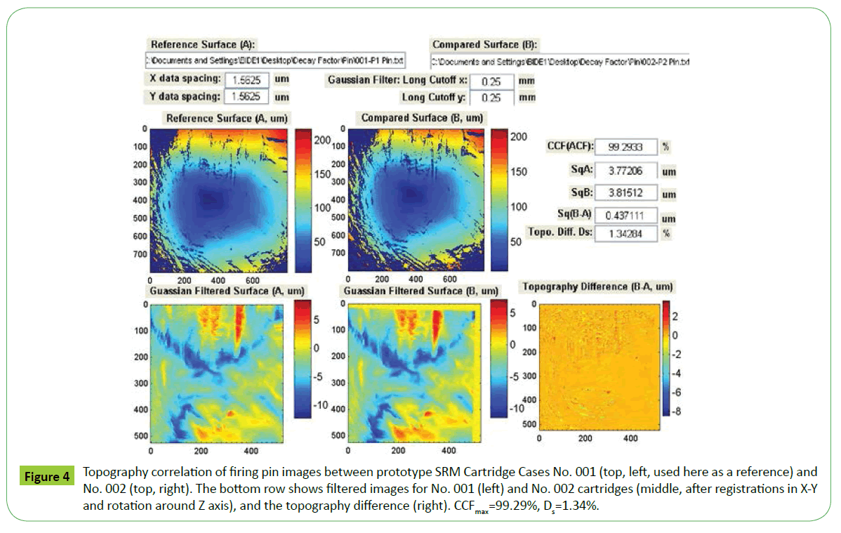
Figure 4 shows a screen output of cartridge case signature measurement. The top two 3D topographies are measured from two prototype Standard Cartridge Cases No. 001 and No. 002. Both are filtered by λc=0.25 mm long wavelength cutoff [21,22], registered along the X- and Y-directions and rotated around the Z-axis until the maximum correlation position is found, see bottom images left and center in Figure 4. Once registered, the 3D CCFmax is calculated to be 99.29% (Figure 4). Meanwhile, a topography difference Z(B–A) is calculated at this position and shown in the bottom right in Figure 4. The signature difference between the two 3D topographies is calculated as Ds=1.34% [6].
Figure 4: Topography correlation of firing pin images between prototype SRM Cartridge Cases No. 001 (top, left, used here as a reference) and No. 002 (top, right). The bottom row shows filtered images for No. 001 (left) and No. 002 cartridges (middle, after registrations in X-Y and rotation around Z axis), and the topography difference (right). CCFmax=99.29%, Ds=1.34%.
Besides the measurements of SRM bullets and cartridges, the 2D/3D Topography Measurement System was used for the NIST Ballistics Imaging Database Evaluation (NBIDE) [23] and the National Ballistics Imaging Comparison (NBIC) project [9]. It has also been used for establishing a measurement traceability and quality control system [8, 9], and for developing an error rate procedure to support nationwide ballistic identifications [10-14].
Establishing a Traceability and Quality System for Nationwide Ballistics Measurements
According to the International vocabulary of metrology – Basic and general concepts and associated terms (VIM) [24], metrological traceability is defined as a property of a measurement result whereby the result can be related to a reference through a documented unbroken chain of calibrations, each contributing to the measurement uncertainty.
From the above definition, three key steps for establishing metrological traceability for ballistics measurements are proposed [8]:
• Establishing a reference standard for ballistics signature measurements. The NIST SRM Bullets and Cartridge Cases are used as a reference standard for both the topography measurements at NIST and the imaging correlations for NIBIN acquisitions [5].
• Establishing an unbroken chain of calibrations from the national laboratories (NIST and the National Laboratory Center of ATF) to local laboratories and customers using the SRM Bullets and Cartridge Cases as reference standards. The unbroken chain of calibration covers both topography measurements at NIST and image correlations at NIBIN. For the topography measurements, the measurement traceability is established using the virtual/physical SRM standard and the proposed parameters—signature difference Ds and crosscorrelation function maximum CCFmax [6]. For the image correlation systems like the Integrated Ballistics Identification System (IBIS) [25], the traceability is established by image acquisitions of SRM Bullets and Cartridge Cases at local IBIS sites, and correlations with the image standard, termed the “Golden Images” [9] established on the IBIS at the National Laboratory Center of ATF.
• Evaluating measurement uncertainty and error rate, establishing control limits and error rates for both the topography measurements and imaging correlations [9, 11, 14].
In order to establish a Nationwide Traceability and Quality System for ballistics identifications in the United States, the National Ballistics Imaging Comparison (NBIC) project was initialized in 2008 [9]. A total of 19 ballistics examiners from 13 U.S. crime laboratories participated in this project. They each took 24 acquisitions of NIST SRM Bullets and Cartridge Cases over the course of a year. The acquired images were correlated with the Golden Images at the National Laboratory Center of ATF, from which control charts and control limits were developed and used for promoting the proposed Traceability and Quality System in NIBIN [9].
Developed a Congruent Match Cells (CMC) Method for Ballistics Identification and Error Rate Estimation
Accurate ballistics identification depends not only on image quality, but also on the capability of correlation software to identify the “valid correlation areas” and to eliminate the “invalid correlation areas” [10-14] from calculations. Currently, the final determination of a match (identification) or non-match (exclusion) in ballistics comparisons is mainly based on visual comparisons made by an examiner having the experience required to exclude invalid correlation areas.
The Congruent Matching Cells (CMC) method developed at NIST systematically divides measured 3D forensic topographies and optical images into “correlation cells.” The CMC method is based on correlations of pairs of small correlation cells instead of correlations performed on the entire images. This is done because a firearm often produces characteristic marks of the ballistic signature, or “individual characteristics” [1], on only a portion of the surface termed “valid correlation area” [10-14], that can be used effectively for firearm identification. Conversely, a region of the surface topography that does not contain individual characteristics of the firearm’s ballistic signature is termed an “invalid correlation region” [10-14], which should not be considered during firearm identification. Invalid correlation areas can occur, for example, due to insufficient contact between the firearm surface and the bullet or cartridge case during firing. The use of small correlation cells allows the CMC method to separate valid and invalid correlation cells in a manner similar to forensic examiners.
The Congruent Matching Cells are determined by both the topography similarity of each compared cell pairs and their pattern similarity of the cell distributions in the two compared topographies. Three sets of identification parameters are derived for identifying compared cell pairs originating from the same source: the cross correlation function maximum CCFmax is used for quantifying topography similarity of each compared cell pairs; while the spatial registration positions in x-y and registration phase angle θ are used for quantifying similarity of the cell distribution patterns [10, 11]. When the values of the three sets of identification parameters (CCFmax, x-y and θ) are within the range of the corresponding thresholds TCCF, Tθ, Tx and Ty, the compared cell pair is qualified as a CMC [10, 11]. For the two compared topographies, if the number of the congruent marching cell pairs is large enough, say CMC ≥ 6, the two topographies can be considered with sufficiently topography similarity and therefore, can be identified from the same source with an acceptable error rate. (Detailed information can be found in [11] and [14]).
An initial validation test of the CMC method was conducted using a set of cartridge cases that has achieved prominence in the firearms identification community when it was produced for a study of visual firearm identifications by ballistics examiners initiated by Fadul et al. at the Miami-Dade Crime Laboratory [26]. The set contains 40 cartridge cases ejected from handguns with 10 consecutively manufactured pistol slides. Ballistics correlations involving a population of consecutively manufactured gun parts represent the most challenging scenario for testing the capability to accurately identify bullets or cartridge cases as being fired or ejected from the same firearm, because the consecutively manufactured gun parts could produce mostly similar surface topographies on the fired bullets and ejected cartridge cases [26].
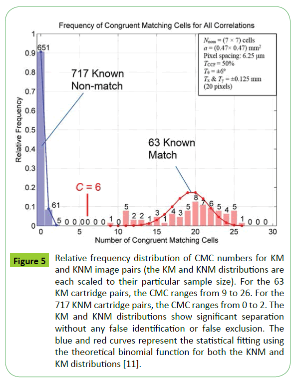
One of the validation test results is shown in Figure 5, that includes 780 pair-wise topography image comparisons of breech face impressions: 63 image pairs came from known match (KM) images; 717 image pairs came from known non-match (KNM) images [12]. The nominal number, Nnom, of compared cell pairs for each topography correlation equals 49 (for a 7 × 7 cell array). The number N of compared effective cell pairs for each correlation, i.e. cell pairs containing a reasonable number of pixels, depends on the common domain of each topography pair. On average for this study, 26 cell pairs were correlated for each image correlation. The cell size a, the pixel spacing, and the thresholds TCCF, Tθ, Tx and Ty are shown on the upper right side of Figure 5. Test results show that the number of congruent matching cells (CMCs) for the 63 KM image pairs ranges from 9 to 26, while the number of CMCs for the 717 KNM image pairs ranges from 0 to 2 (Figure 5). There is a clear separation between the KM and KNM distributions, meaning that the CMC method didn’t produce any false identification or false exclusion.
Figure 5: Relative frequency distribution of CMC numbers for KM and KNM image pairs (the KM and KNM distributions are each scaled to their particular sample size). For the 63 KM cartridge pairs, the CMC ranges from 9 to 26. For the 717 KNM cartridge pairs, the CMC ranges from 0 to 2. The KM and KNM distributions show significant separation without any false identification or false exclusion. The blue and red curves represent the statistical fitting using the theoretical binomial function for both the KNM and KM distributions [11].
Additional validation tests for the proposed CMC method include optical intensity image correlations of the same set of 40 cartridge cases [13], and using a completely different large set of sequentially manufactured firearm slides which consist of 95 cartridge cases with a total of 4465 pair-wise image correlations [14]. From these additional tests, all the KM and KNM image pairs show significant separation without any false identification and false exclusion [13,14].
The CMC method also enables an approach to estimating error rates based on statistical analysis of the total number of correlation cells, the number of the Congruent Match Cells (CMC), and the statistical distribution of three sets of identification parameters [11]. Based on these test results, statistical models are developed for error rate reporting [14].
The proposed CMC method can be used for correlation of both geometrical topographies [12] and optical images [13], and can be potentially applied for all case scenarios of fired cartridge cases (including breech face, firing pin and ejector mark), fired bullets, and tool marks. The CMC parameters and algorithms are in the public domain and subject to open tests. Based on the CMC method, an error rate procedure is proposed for establishing a statistical foundation to support nationwide ballistics identifications in forensic science [11,14], and to potentially provide an error rate report for court proceedings, in a manner similar to the method used for reporting the Coincidental (Random) Match Probability (CMP or RMP) in forensic identification of DNA evidence [3,4]. The proposed CMC method and error rate procedure may also serve as a foundation for manufacturers to develop the Next Generation Ballistic Identification System characterized by high correlation accuracy and error rate reporting, which would represent a decided advance over current automated ballistic identification systems. An error rate procedure could also be used for laboratory assessment and accreditation in accordance with the ISO 17025 standard [27] and ASCLD/ LAB procedures [28,29].
We envision a time when ballistic examiners can input either topographies or optical intensity images into a program that automatically conducts correlations using the CMC method, and displays the correlation conclusion (matching or non-matching) with an error rate report. The CMC method and statistical analysis can provide a scientific foundation and a practical method to estimate error rates for supporting ballistic identifications in forensic science.
Summary
Surface and topography metrology provides strong support to firearm evidence identifications in forensic science. Based on the research projects in surface metrology and standardization, researchers at NIST developed SRM Standard Bullets and Cartridge Cases and a 2D/3D Topography Measurement System. They formulated a Traceability and Quality System for ballistics identifications within the National Integrated Ballistics Identification Network (NIBIN) in the United States. They proposed a Congruent Match Cells (CMC) method for accurate firearm evidence identification, which can provide a statistical foundation and practical method for estimating error rate to support firearm evidence identification in forensic science. The CMC method and error rate procedure can be used for promoting the Next Generation Ballistics Identification System characterized by conclusive identification (or exclusion) with error rate report, in a similar way that reporting procedures have been established for forensic identification of DNA evidence [3,4].
Acknowledgement
The authors are grateful to Dr. T V Vorburger, Dr. R M Silver, Dr. J A Soons, Ms. S Ballou, Mr. R M Thompson, Dr. L Ma, Mr. T B Renegar, Mr. A Zheng, Mr. R Clary, Mr. E Whitenton, Mr. D. Kelly, Dr. W. Chu, Dr. H. Zhang and Mr. M Tong of NIST, and Mr. P Rubert of Rubert + Co. Ltd. in UK for their contributions in the NIST projects; and to Dr. T V Vorburger, Dr. L Ma and Dr. D B Ott for their comments and suggestions during the review process.
References
- Scientific Working Group for Firearm and Toolmarks (SWGGUN)The Foundations of Firearm and Toolmark Identification.
- Vorburger TV, Song J, Petraco N (2015) Topography measurements and applications in ballistics and tool mark identifications, Surface Topography: Metrology and Properties, Topical review.
- Ballistic Imaging, the National Research Council (2008).
- Strengthening Forensic Science in the United States-A Path Forward, the National Research Council(2009).
- Song J, Whitenton E, Kelley D, Clary R, Ma L, et al. (2004) SRM 2460/2461 standard bullets and cartridge cases project. J Res NatlInst Stand Technol 6: 533-542.
- Song J, Vorburger TV (2000) Proposed bullet signature comparisons using autocorrelation functionsToronto.
- Ma L, Song J, Whitenton E, Zheng A, Vorburger TV (2004) NIST bullet signature measurement system for Standard Reference Material (SRM) 2460 Standard Bullets. Journal of Forensic Sciences 4: 649-659.
- Song J, Vorburger TV, Ballou S, Ma L, Renegar TB, et al. (2010) Three steps towards metrological traceability for ballistics signature measurements.Measurement Science Review1:19-21.
- Song J, Vorburger TV, Ballou S, Thompson RM, Yen J, et al. (2012) The national ballistics imaging comparison (NBIC) project. Forensic Science International 216: 168-182.
- Song J (2013) Proposed NIST ballistics identification system (NBIS) based on 3D topography measurements on correlation cells. AFTE Journal 2: 184-194.
- Song J (2015) Proposed Congruent Matching Cells (CMC) method for ballistics identification and error rate estimation. AFTE Journal 3: 177-185.
- Chu W, Tong M, Song J (2013) Validation tests for the Congruent Matching Cells (CMC) method using cartridge cases fired with consecutively manufactured pistol slides. AFTE Journal 4: 361-366.
- Tong M, Song J, Chu W, Thompson R M (2014) Fired cartridge case identification using optical images and the Congruent Matching Cells (CMC) Method. Journal of Research of NIST 119: 575-582.
- Song J, Vorburger TV, Chu W, Yen J, Soons JA, et al. Estimating error rates for firearm evidence identifications in forensic science, passed NIST review, to be submitted for publication.
- Teague E, Scire F,Vorburger TV (1982) Sinusoidal profile precision roughness specimens. Wear 61: 61-74.
- Song J, Evans C, McGlauflin M, Whitenton E, Vorburger TV, et al. (1998) NIST virtual/physical random profile roughness calibration standards, in Proc. SPIE’98. Scattering and Surface Roughness213-221.
- Song J, Vorburger TV,Rubert P (1992) Comparison between precision roughness master specimens and their electro-formed replicas. Precision Engineering 14: 84-90.
- Rubert P (2000)Properties of electroformed calibration standards for surface topography measurement systemsin X. International Colloquium on Surfaces 245-251.
- Song J, Rubert P, Zheng A,Vorburger TV (2008) Topography measurements for determining the decay factors in surface replication. Measurement Science and Technology1-4.
- Song J, Chu W, Vorburger TV, Thompson R, Yen J, et al. (2012) Development of ballistics identification –From image comparison to topography measurement in surface metrology. MeasSciTechnol 4: 6.
- Geometrical Products Specifications (1996) Surface texture: Profile method – Metrological characteristics of phase correct filters. International Organization for StandardizationGeneva.
- Surface Texture (Surface Roughness Waviness and Lay) (2012) New York.
- Vorburger TV, Yen J, Bachrach B, Renegar TB, Filliben J, et al. (2007) Surface topography analysis for a feasibility assessment of a National Ballistics Imaging Database.
- International vocabulary of metrology - Basic and general concepts and associated terms (VIM) (2008).
- The Integrated Ballistics Identification System (IBIS). Forensic Technology Inc Montreal Canada.
- Fadul TG, Hernandez GA, Stoiloff S,Gulati S (2012) An empirical study to improve the scientific foundation of forensic firearm and tool mark identification utilizing 10 consecutively manufactured slides Pro Rep. National Institute of Justice.
- General requirements for the competence of testing and calibration laboratories (2005) Geneva.
- The American Society of Crime Laboratory Directors/Laboratory Accreditation Board (ASCLD/LAB), Measurement traceability policy.
- WellerTJ, Zheng A, Thompson R, Tulleners F (2012) Confocal Microscopy Analysis of Breech Face Marks on Fired Cartridge Cases from 10 Consecutively Manufactured Pistol Slides. J Forensic Sci 57: 912–917.
Open Access Journals
- Aquaculture & Veterinary Science
- Chemistry & Chemical Sciences
- Clinical Sciences
- Engineering
- General Science
- Genetics & Molecular Biology
- Health Care & Nursing
- Immunology & Microbiology
- Materials Science
- Mathematics & Physics
- Medical Sciences
- Neurology & Psychiatry
- Oncology & Cancer Science
- Pharmaceutical Sciences
