Measurement and Characterization of Flexible Absorbing Materials for Applications in Wireless Communication
Tian Zhou*, Dong Wel, Songtao Yang, Guanxiong Xu, Chunlin Ji and Zhiya Zhao
DOI10.21767/2472-1948.100007
1Kuang-Chi Institute of Advanced Technology, Software Building, No.9 Gaoxin Zhong 1st Road, High-Tech Industrial Estate, Nanshan District, Shenzhen, Guangdong, P.R. China
2State Key Laboratory of Metamaterial Electromagnetic Modulation Technology, China
- Corresponding Author:
- Tian Zhou
Kuang-Chi Institute of Advanced Technology
Software Building, No.9 Gaoxin Zhong 1st Road
High-Tech Industrial Estate, Nanshan District, Shenzhen
Guangdong, P.R. China
Tel: +86 755 86135700
E-mail: tian.zhou@kuang-chi.org
Received date: February 25, 2016; Accepted date: March 03, 2016; Published date: March 10, 2016
Citation: Zhou T, Wel D, Yang S, et al. Measurement and Characterization of Flexible Absorbing Materials for Applications in Wireless Communication. J Sci Ind Metrol. 2016, 1:7. doi: 10.4172/2472-1948.100007
Abstract
Absorbing materials are widely applied in applications of wireless communication. It is of great importance to measure and characterize these materials efficiently and precisely. In this paper, the author first utilizes transmission line methods to acquire scattering parameters, which are used as input in the parameter retrieval process for EM properties. After successful characterization of these materials, EM properties are imported in commercialized software for simulation of reflectivity. For comparison, NRL arch reflectivity test is conducted and good comparison is found. Discrepancy between the two is analyzed in this paper.
Keywords
Absorbing materials; Parameter retrieval; NRL arch reflectivity test
Introduction
Absorbing materials are widely used in telecommunications, consumer electronics, aerospace, automotive electronics, medical equipment’s, industrial and defense applications, especially in the EMI and EMC reduction and antenna pattern shaping [1,2]. Two common types of absorbing materials are magnetic absorbers and foam absorbers. Magnetic absorbers are usually thin (0.1 to 3 mm) polymeric materials filled with magnetic particles. These materials usually have both high permeability and permittivity, and high magnetic loss and dielectric loss as well [3]. Foam absorbers are consisted of open celled foam impregnated with a carbon coating. These foam absorbers often have larger thickness than magnetic absorbers and even larger thickness for outdoor applications. In this article, since our primary interest is in telecommunication systems, we focus on the measurement and characterization of thin, flexible magnetic absorbers only.
In the measurement and characterization of absorbing materials, common methods include transmission line method and free space method. Transmission line methods involve placing the material under test (MUT) inside a portion of enclosed transmission line. In some sense, the open-ended coaxial probe is a cut off section of transmission line. For the enclosed transmission line, it is usually a section of rectangular waveguide or coaxial airline [4]. It is reported that the major error in transmission line testing is due to MUT preparation, especially for thin, flexible absorbing materials. Free space method comes often in two set-ups: transmission configuration and reflection configuration. For the NRL arch reflectivity test, specific standards have been published, such as ASTM standards in the US and GJB 2038A-2011 in China. In the MUT preparation for NRL arch reflectivity test, size of the MUT is recommended to be larger than 5 λ × 5 λ. It becomes inconvenient for tests conducted at low frequencies such as UHF, both for its relatively large size and surface flatness. In this article, we first measure the S parameters of absorbing materials with transmission line methods. Then the electromagnetic parameters are extracted from S parameters, which served as input for simulation. The simulation model is set up for best match to real scenario of NRL arch reflectivity test, least model complexity and least computational cost. Actual NRL arch reflectivity test is conducted for comparison. For some suppliers in China, the only test conducted is NRL arch reflectivity test. However, if one wants to fully characterize absorbing materials and improve their EM performances, it is recommended that the dispersion properties of the materials can be fully characterize. Correct acquisition of these EM properties is crucial for impedance matching design, mixture ingredients design and material production.
The article is arranged in the following manner: Section II describes the measurement and characterization methods of absorbing materials in detail, including transmission line test with waveguides, S parameter retrieval, EM software simulation and NRL arch reflectivity test. Section III describes the results of the above mentioned methods, compares results from both simulation and measurements and analyzes discrepancies between the two. Section IV discusses the purpose of the article and proposes some suggestions in characterization of thin, magnetic absorbing materials.
Methods
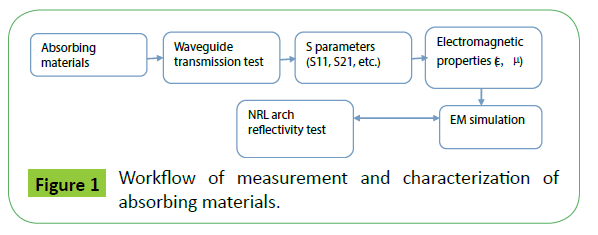
Measurements of absorbing material have been performed for a long history. With new simulation modules and parameters extracted from experiments, one can perform EM simulation and compare to actual testing. After going through the whole process illustrated in Figure 1, one can acquire better understanding of the EM performance of absorbing materials. Through the comparison between simulation and measurement, one can appreciate the whole cycle of measurement and characterization thoroughly.
Before the transmission line test is conducted, samples of the MUT are prepared according to the inner boundary of the corresponding waveguides, as shown in Table 1. Size of the sample is of critical importance so that a tight fit with the waveguide is possible. Oversized sample may cause buckling, which can contribute substantially to incorrect characterization. For applications in 3G and 4G networks in China, we select the frequency from 1.72 to 2.61 GHz. The size of the MUT is 109.2 mm by 54.6 mm, whose pictures are shown in Figure 2. The model of the vector network analyzer is Agilent N5222A (now Keysight, frequencies up to 26.5 GHz). The version of the materials measurement software used is Agilent 85071E. And the type of straight waveguides in the system set up is HD-22WAL44 (HengDa Microwave Inc.), as shown in Figure 3(a). S parameters acquired from the transmission line method are imported to Agilent 85071E materials measurement software for parameter retrieval. Readers who are interested in the retrieval process can refer to [5,6]. Thickness of the MUT is recorded as 2.06 mm, which satisfied the requirements according to ref [7]. It points out that thickness of the MUT is irrelevant to the retrieved material properties, and kL«1is recommended.
| Waveguide type | Frequency range/GHz | cross section length(a)/mm | cross section width(b)/mm |
|---|---|---|---|
| HD-14WAL66 | 1.13~1.73 | 165.1 | 82.6 |
| HD-22WAL44 | 1.72~2.61 | 109.2 | 54.6 |
| HD-32WAL29 | 2.60~3.95 | 72.1 | 34.0 |
| HD-48WAL19 | 3.94~5.99 | 47.5 | 22.1 |
| HD-70WAL14 | 5.38~8.17 | 34.8 | 15.8 |
| HD-100WAL9 | 8.20~12.4 | 22.9 | 10.2 |
| HD-140WAL6 | 11.9~18.0 | 15.8 | 7.9 |
Table 1: Requirements of size of MUT
The extracted EM properties of the absorbing material are imported to commercialized EM simulation software for further investigation. In the simulation, the reflectivity of the absorbing material backed with metal plate is obtained. The ‘unit cell’ simulation module is used to mimic a finite flat surface repeat itself to infinity [8]. The module is widely used for simulation of periodic structures such as antenna arrays and Metamaterial. Distance between two consecutive unit cells and ‘grid angle’ can be specified in the simulation. The detailed simulation model is shown in Figure 4. The size of the ‘unit cell’ is set as 5 mm by 5 mm, an arbitrary number for homogeneous materials. Thickness of the absorbing material is set as 2 mm and that of the metal plate is 2 mm, which are settings used in the following NRL arch reflectivity testing. The working frequency is from 0.8 to 2.7 GHz in the simulation. The EM properties of the absorbing materials at frequencies lower than 1.72 GHz is extrapolated with first order model fitting from the measured properties. Tetrahedral mesh is used in the model with an accuracy of 1e-4 in the solver setting. Total number of tetrahedrons is 636. S11 parameters can be obtained from the simulation with electromagnetic waves incident perpendicularly to the surface of the absorbing material. Total simulation time is 154 seconds, thanks to the ‘unit cell’ simulation module. Details on the simulation procedures can refer to [8]. The simulated parameters are then compared with the actual NRL arch reflectivity testing.
The NRL arch reflectivity test is the industry standard for testing the reflectivity of materials, which is originally designed by the US Navy Laboratory [9]. Our arch testing system is built according to GJB 2038A-2011, a Chinese national standard for reflectivity testing of absorbing materials (Figure 3b). The system integrates both reflection test and transmission test of dielectric and magnetic materials. Size of the anechoic chamber is 4 m by 3.5 m by 5 m and radius of the arch is 2 m. The model of the horn antennas is XB-WDB-1-18N with a working frequency from 1 to 18 GHz. The network analyzer is Agilent-N5222A (10 MHz - 26.5 GHz). According to the standard, size of the MUT is recommended to be at least 10 λ of the lowest working frequency. However, the recommendation is not applicable in some cases for testing in the UHF band. In practice, sample size greater than 600 mm by 600 mm is recommended for frequencies from 1 GHz to 3 GHz. The absorbing material with 600 mm length and 2 mm thickness is placed on a metal plate with the same size and thickness. Air gap between the layers is removed with our best effort to eliminate errors in the testing. No difference in reflectivity between the TE and TM mode is observed in the normal incidence, since the absorbing material is isotropic in the x and y direction in the surface plane. Reflectivity from metal plate is also recorded for calibration. Results are shown in the next section and compared with previous simulation.
Results
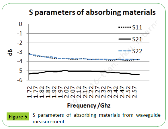
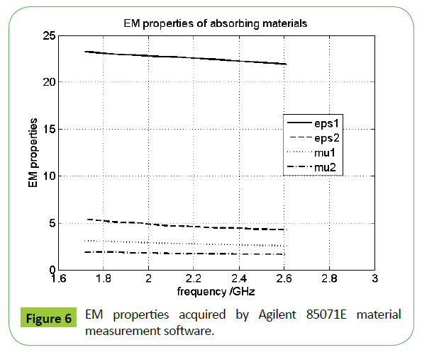
Transmission line method for acquisition of absorbing materials is robust and widely applied. S parameters from 1.72 to 2.61 GHz from the waveguide testing are shown in Figure 5. S11 and S22 parameters are equivalent for homogenous materials, which can be different for inhomogeneous or multi-layer materials, especially for asymmetric Metamaterial [7]. EM properties acquired by Agilent 85071E material measurement software is shown in Figure 6. The properties are retrieved from S parameters with close form algorithms such as Nicolson-Ross [10]. NIST model cannot apply since the MUT in this case is magnetic [11].
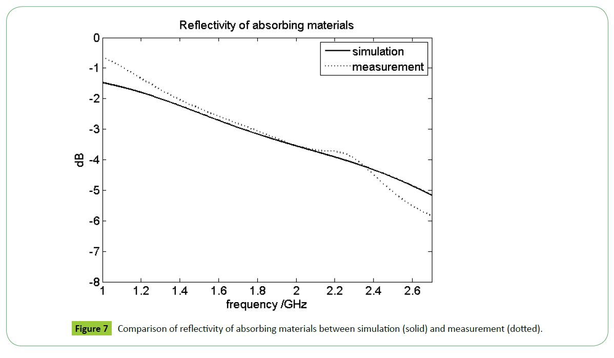
Simulation results of S11 parameter of an infinitely large absorbing materials backed with matel plate is shown in solid line in Figure 7, while easurement results from NRL arch reflectivity test is shown in dotted line. Reflectivity is defined as the reduction in reflected power caused by the introduction of an absorbent material, while S11 parameter is the reflection coefficient seen looking into port 1 when all other ports are terminated in matched loads [12]. Although reflectivity is measured in terms of power and S parameters in terms of field strength, both are comparable when converted to decibels (dB).
As is shown in Figure 7, good comparison is observed between measurement from NRL arch reflectivity test and simulation with actual EM properties of the material. One has to note that the comparison is made under two assumptions. The first assumption is that reflection from the infinitely large surface in the simulation is equivalent to reflection from finite surfave surrounded by pyramid absorbing material, settings in an NRL arch reflectivity test. The second assumption is that first order model fit is used in the extrapolation of EM properties at frequencies from 1 to 1.72 GHz. The second assmption can be validated with actual transmission test, but is not conducted here due to lack of necesary horn antennas. As can be observed from Figure 7, good match is found between simulation and measurement data with an average error of 0.28 dB.
Discussion
The purpose of this paper is to provide a systematic way of measurement and characterization of absorbing materials. And to provide a simulation method which is comparable to real NRL arch reflectivity test. The simulation is by no means trying to substitute or avoid real measurement, but to provide an option for early evaluation and fast characterization. Measurements mentioned in this article are mature and should be conducted by corresponding standards. The simulation method is enlightened by full wave simulation of Metamaterial. Discrepancies between the two are analyzed in last section.
Simulation model designed with exact setting of the NRL arch reflectivity test is not conducted. With the large surface area and pyramid absorbing material in place, the computational cost is expected to be very high. The simulation method used in this article, however, takes less than 3 mins.
More work can be done based on the research described in this article. For example, comparison of reflectivity from different incident angles between simulation and measurement can be conducted. Multiple layer absorbing materials can be investigated. Reflection and transmission properties of Metamaterial can be investigated with transmission line method and free space method in both simulation and measurement.
The measurement and characterization method is useful for researchers, manufactures and end users related to absorbing materials for wireless communication.
Acknowledgement
The authors would like to thank Mr. Peng Huang for data processing and valuable discussions.
Funding
This study is supported by State Key Laboratory of Meta-RF Electromagnetic Modulation Technology (No.2011DQ782011); Shenzhen Key Laboratory of Meta-RF Fabrication and Packaging (No. CXB201109210102A); Shenzhen Innovative R&D Team Program (Peacock Plan) (No.KQE201106020031A).
Competing and Conflicting Interest
Tian Zhou, Dong Wei, Songtao Yang, Guanxiong Xu, Chunlin Ji and Zhiya Zhao declare that they have no conflict of interest or financial conflicts to disclose.
References
- Petrov VM, Gagulin VV (2001) Microwave absorbing materials. Inorganic Materials37: 93-98.
- Vinoy KJ, Jha RM (1996) Radar absorbing materials- From theory to design and characterization. Boston MA: Kluwer Academic Publishers.
- www.lairdtech.com
- https://literature.cdn.keysight.com/litweb/pdf/5991-2171EN.pdf?id=2326291
- Weir WB (1974) Automatic measurement of complex dielectric constant and permeability at microwave frequencies. Proceedings of the IEEE 62: 33-36.
- Nicolson AM, Ross GF (1970) Measurement of the intrinsic properties of materials by time-domain techniques. Instrumentation and Measurement IEEE Transactions 19: 377-382.
- Smith DR, Vier DC, Koschny T (2005) Electromagnetic parameter retrieval from inhomogeneous Metamaterial. Physical Review E 71: 036617.
- https://www.cst.com/Applications/Article/Modeling-Metamaterials-Metamaterial-Development-Using-Electromagnetic-Simulation
- https://www.eccosorb.com/Collateral/Documents/English-US/nrl_arch_reflectivity_testing.pdf
- Nicolson AM, Ross GF (1970) Measurement of the intrinsic properties of materials by time-domain techniques. Instrumentation and Measurement IEEE Transactions 19: 377-382.
- https://www.keysight.com/upload/cmc_upload/All/FreeSpaceSeminarRev2.pdf
- Pozar DM (2009) Microwave engineering. John Wiley & Sons.
Open Access Journals
- Aquaculture & Veterinary Science
- Chemistry & Chemical Sciences
- Clinical Sciences
- Engineering
- General Science
- Genetics & Molecular Biology
- Health Care & Nursing
- Immunology & Microbiology
- Materials Science
- Mathematics & Physics
- Medical Sciences
- Neurology & Psychiatry
- Oncology & Cancer Science
- Pharmaceutical Sciences
